MiniBMS install
For those not familiar with charging Lithium batteries, a Lithium battery charger usually has battery management built in. If you look at a Lithium Makita drill battery there are multiple pins for the charger to monitor the voltage of each cell. Without this management, an unbalanced pack can result in one cell getting over charged, or over discharged. I have been manually balancing my cells for the last year, and finally decided to buy MiniBMS.The cost was $1200 for everything to manage 99 cells. The BMS will burn up excess current to the cells which are fully charged, allowing the remaining cells to get topped off. Eventually, this results in a perfectly top balanced pack. There is also a serial link dry contact which I call "pack healthy". If all the batteries are in their normal voltage range, the contact is closed. If one or more cells voltage is too high or low, the contact opens. This alarm condition can be used to disconnect the charger, or sound a buzzer to protect the pack from damage.
 MiniBMS Distributed version. 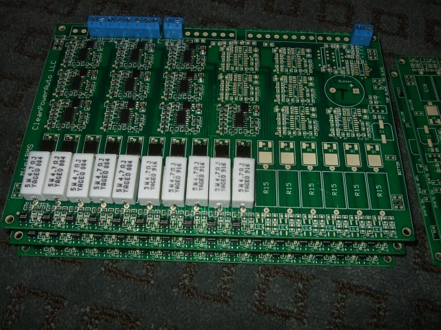 MiniBMS Centralized verison.  The MiniBMS interface board and solid state relay for disconnecting the AC power to the battery charger. |
 The included ring lugs were one size too large for my 100Ah cells. I swapped the 3/8" lugs for 5//16". 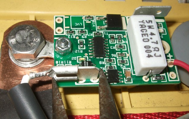 The spade connectors are an extremely tight fit, I used needle nose pliers to press them on so I didn't stress the solder pads on the circuit board.  Installed MiniBMS.  The green lights indicate the cell voltage is normal (not high alarm or low alarm state). A red light indicates shunt balancing is activated.  |
 The MiniBMS boards (central version) stack using suitcase jumpers for mechanical support, as well as connect the serial "Pack Healthy" link. The manual says to zip tie the boards together, but I couldn't trust these jumpers to be ruggedized for an automotive environment. I spent a day making plastic mounting plates which rigidly mount all the boards together.  The boards stack with a 0.1" offset, so the mounting brackets have offset holes. |
 Distributed BMS installed. I have a fuse for each battery connection to the BMS, the white wire duct keeps the wires organized and hidden.  Picture of my trunk with the Distributed MiniBMS installed.  The battery connections (63 cells in all) to the Distributed MiniBMS. Since my mounting plates block the air flow from the sides, I can install a fan to direct air across the power resistors.  I installed a shelf to mount my BMS, the interface board, and solid state relay. |
Now that I've been using the BMS for about a week I have some constructive criticism. The centralized boards need a fan. The resistors are packed in so tight, that all four sides are surrounded by other resistors. There is no where for the heat to escape. The resistors reached 200F in a matter of minutes with very minimal shunting current. The centralized boards are not as accurate as the distributed boards. The current pulses from the PWM of my charger falsely trigger the shunting circuit. As a result some cells begin shunting at 3.4 volts instead of 3.5 volts. The distributed boards don't seem to be as prone to noise issues, so these all begin shunting at 3.5 volts. Part of the issue may also be the sharing of battery connections with adjacent BMS circuits. Current flowing though one wire will cause a voltage drop, which appears as a voltage rise to the next BMS circuit. I'm using 16 awg wire, so the most voltage drop should be 20mV at full shunting current. |